What this measures
This is a Rayleigh match. With normal color vision you can mix red and green light until it looks identical to a yellow — two different spectra that produce the same signal in your cones (a metamer).
The interesting number is not the mixture you settle on, but how wide a range of mixtures you accept as "the same yellow." Most people accept a fairly wide band. A tetrachromat — someone with a fourth cone type — breaks that metamer and accepts a narrower band. The width of your matching range is the signal.
Testing for tetrachromacy
Most people are trichromats: three cone types (roughly red, green, blue). A small number — almost always women, through X-linked variation in the cone-opsin genes — carry a fourth cone type, with a sensitivity tucked between the usual red and green. If that fourth cone actually feeds perception, the person is a functional tetrachromat and can make color distinctions the rest of us can't.
Why the Rayleigh match finds them
The test asks you to mix red and green light until it matches a yellow. For a trichromat this works because red + green can produce the same cone signals as the yellow — a metamer, two different spectra your eyes can't tell apart. A fourth cone gets a different signal from the red-green mix than from the pure yellow, so the metamer breaks.
The tell isn't which mixture you pick — it's how wide a range of mixtures you'll accept as matching. A trichromat accepts a broad band; a functional tetrachromat accepts a narrow one (or rejects a match a trichromat is happy with). The width of your matching range is the signal. The test brackets both edges (method of limits) and reports it.
What it can and can't say
- It's a screening tool, not a diagnosis. Carrying a fourth opsin gene is fairly common; using it perceptually is rare. This test probes the using, not the carrying.
- A narrow range is suggestive, not proof — attention, room light, and device calibration all move it. That's why we repeat trials, keep a normal-observer baseline, and record each device's calibration.
Contributing your result coming soon
With your consent, the test will let you submit your matching-range width, your device's calibration (so home-built rigs are comparable), and a little non-identifying context — never your name. Aggregated, it becomes an open dataset on how differently people see, and a way to surface candidate tetrachromats for follow-up. Always opt-in: you can run the test and keep your data entirely local.
Build the device
A fork of the BrainardLab Penn Anomaloscope: an Arduino Leonardo driving a yellow LED and an RGB LED, behind an orange long-pass filter and a diffuser.
- Board: Arduino Leonardo. LEDs: yellow → D9 (100 Ω), RGB red → D6 (150 Ω), green → D5 (100 Ω), blue → D3 (unused).
- Firmware: flash
anomaloscope_leonardo.ino(dumb actuator:R/G/Y 0–255over serial, 9600 baud). - Filter (required): an orange long-pass with cut-on between 546 and 589 nm — Rosco #23, Kodak/Tiffen Wratten 23A, or Lee 780 Golden Amber. Plus a diffuser (Scotch tape over the LEDs).
- Then: Connect above, Calibrate, and Run the test.
↓ Lid cutting template (SVG — print at 100%) — two 1.5" windows, centerlines, septum mark.
Full BOM, wiring, and CAD are in the project repo. (Build-guide page expands in a later phase.)
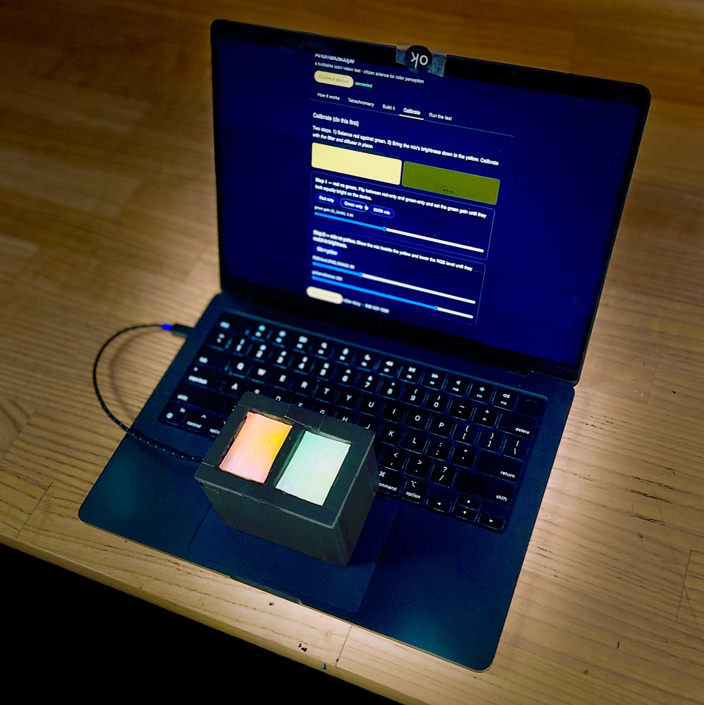
Calibrate (do this first)
Two steps. 1) Balance red against green. 2) Bring the mix's brightness down to the yellow. Calibrate with the filter and diffuser in place.
- Balance: set
G_GAINuntil the red and green bands look equally bright. - Filter check: look through the orange filter too — the green band should drop well below the red.